DefaultPageTemplate.ascx

A GUIDE TO DIMMER SWITCHES
Introduction
Our rotary dimmers and dolly dimmer switches are trailing edge. Trailing-edge dimmers are more sophisticated than leading-edge dimmers as they benefit the user with smooth, silent dimming control, absent of any buzzing noise.
Trailing-edge dimmers have lower minimum load than leading-edge dimmers, making them a better choice for dimming modestly sized low-powered lighting circuits.
Particularly beneficial for incandescent and halogen bulbs is the 'soft start?' feature which prevents filament bulbs from dying or exploding of thermal shock when first switched on.
Important to note
You must observe the recommended maximum load:
1 -10 LED lamps (bulbs)
LED and Halogen - Max load 120W
Our dimmer switches are not suitable for non-dimmable LED lighting, fluorescent bulbs & tubes, or fans.
PLEASE READ THE FOLLOWING GUIDE LINES TO ENSURE SAFE AND SUITABLE APPLICATION
Overview
The integrated Trailing-edge dimmer modules that we use are supplied by V-Pro. Use only on an electricity supply of 200-250 volts AC.
IMPORTANT
Read ALL sections below before installing this dimmer switch.
Our dimmers are set to run in trailing-edge mode (MODE 1) by default. This versatile mode is suitable for most types of lighting, including many dimmable LEDs. It is also gentler on the load.
An alternative trailing-edge mode (MODE 3) may improve the performance of some dimmable LEDs and dimmable CFLs. Some other lighting loads, including some types of LED, perform best with leading-edge control. This dimmer can also be set to run in leading edge (MODE 2) with certain types of LED light. To change the mode, follow the instructions under 'Programming' below.
To optimise the dimming range for LED lighting in particular the minimum brightness setting of the dimmer can be adjusted see 'Adjusting the Minimum Brightness' under 'Programming'. This product complies with European Safety Regulations (IEC 669-2- 1 or BSEN 60669-2-1) when used in lighting circuits containing MCBs (miniature circuit breakers).
These can be rated at 6A, 10A or 16A (preferably 6A for lighting circuits). Your guarantee is not affected if you have an older lighting circuit protected by fuse wire links.
Loading
Mixed loads
Please adhere to 'dimmable LED?' advice when using mixed loads
This switch is suitable for:
Dimmable LED lighting
Mains voltage incandescent GLS or candle-shaped bulbs
Good quality dimmable electronic low voltage transformers (including those requiring trailing-edge control - see 'transformers')
GU10 or similar good quality mains halogen bulbs
Dimmable CFLs
This switch is not suitable for:
Non-dimmable LED lighting
Non-dimmable fluorescent bulbs and tubes
Wire-wound or toroidal transformers
Electric motors (e.g. fans)
TRIAC dimmable drivers (Choose V-Com series dimmers)
Overload Protection
This dimmer switch is protected against overload. If an overload occurs it will automatically turn off until the overload is removed and the dimmer switch is switched off and then switched back on again. However, if the dimmers witch receives a total short-circuit it may be damaged beyond repair.
Transformers
Use only with quality dimmable electronic transformers. For optimum performance choose our transformers. Do not use with wirewound or toroidal transformers.
To calculate load, add the va ratings of the transformers (not the wattage of the bulbs). Choose transformers with a maximum rating close to their lamp load (e.g. use a 50va, 60va or 70va transformer to control a 50w low voltage bulb).
N.B. certain transformers may not behave according to their power rating when used with a dimmer. An overload will result in the safety features switching the dimmer off. If so, change your transformer(s) (our transformer(s) recommended); or remove one (or some) transformer(s) from the circuit; or choose a higher rated dimmer. Maximum loads for dimmer switches. Always observe the recommended maximum load.
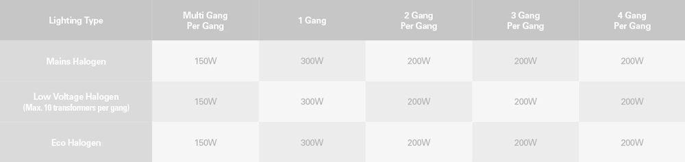
Maximum of 10 lamps for GLS and Halogen loads
Dimmable LED 1 to 10 LEDs (max 120W)
Dimmable CFL For 1 to 8 CFLs (use mode 3)
Fitting your Dimmer Switch
Read the instructions below carefully. Incorrect installation may damage the dimmer beyond repair. In case of any doubt or difficulty consult a qualified electrician.
1. Switch off at the mains, then remove the existing switch and disconnect the wiring from the switch terminals at the rear, taking note of the present wiring of the switch and the marking on the terminals. Where there are two or more wires together in the old switch, they must be kept together in the dimmer switch.
2. Ensure that any wall box is free of plaster lumps or projecting screw heads. Dimmer switches on single-sized plates can be fitted to wall boxes having 60.3mm screw fixing centres and those with double-sized plates to wallboxes with 120.6mm fixing centres. Most models can be fitted into a box with a minimum depth of 25mm. A box having 4 fixing lugs cannot be used without modifying it. The top and bottom lugs must be broken off or bent flat.
3. To connect the wiring for 1-way or 2-way circuits refer to the diagrams to the right under the heading '1-Way, 2-Way and Multi-Way Circuits'. Take care that no bare wires project out of the terminals. Keep wires together in a terminal if they were together in your old switch.
4. Dimmer switches having a metal plate must be earthed by means of the earthing point on the dimmer.
5. After connecting the wires screw the dimmer switch gently into the wall box so that the front plate is not distorted or cracked. Do not trap the wiring between the rear of the dimmer and the back of the wall box.6. Once installation is complete. Switch on the mains supply and switch on the dimmer.
Important: Disconnect the dimmer before carrying out insulation resistance testing. Failing to do so could damage a dimmer and make the guarantee invalid.
Programming
Optimising the performance of your dimmer switch.
When you first install the dimmer switch it will automatically default to trailing-edge mode
1. This mode is the best one for most types of lighting but for some lighting loads you may be able to improve the dimming performance by changing the driving mode. (See 'changing the driving mode' below.) You can always reset to trailing-edge mode 1.
Additionally, the minimum brightness setting of the dimmer can be adjusted to achieve the optimum dimming range for a particular load as follows. (You may also need to refer to these instructions if you change your lights to a different type at a later date so please keep them for reference).
Adjusting the minimum brightness
If your lights are flickering when they are dimmed to a low level you can increase the minimum brightness setting of the dimmer, which may prevent this from happening. If the lights are brighter than you would like when the dimmer is set to minimum, you can try reducing the minimum brightness setting of the dimmer.
1. Switch on and set the dimmer knob to the minimum position (turn fully anti-clockwise).
2. Turn the lights off and back on again. Off - on, roughly once per second.
3. Repeat step 2 at least twice more. Off - on - off - on, roughly once per second.
4. The lights will step up and down in brightness to show that the dimmer is in configuration mode, then either stay at a low light level or go off.
5. Turn the knob fully clockwise. The lights will come on and allow you to adjust the minimum brightness.
6. Adjust the brightness that you are happy with as the minimum. Leave the dimmer in this position.
7. After 3 seconds the dimmer will notice that you have stopped adjusting the minimum. The lights will step up and down in brightness to show that the dimmer has returned to normal operation.
8. Continue to use the dimmer as normal, with your new minimum brightness.
Changing the driving mode
You may be able to improve the performance of your lamps by changing the driving mode to mode 3, or with some types of lamp mode 2.
NB. It has been noted that some LEDs do not show the programming as well as others. If you are having difficulty seeing the programming steps, you can replace one LED lamp with a halogen one for the duration of the programming in order to see the steps more clearly.
1. Switch on and set the dimmer knob to the maximum position (turn fully clockwise).
2. Turn the lights off and back on again. Off - on, roughly once per second.
3. Repeat step 2 at least twice more. Off - on - off - on, roughly once per second.
4. The lights will step up and down in brightness to show that the dimmer is in configuration mode, then either stay at a low light level or go off.
5. To select mode 3, first turn the knob fully anti-clockwise then fully clockwise. For mode 2, just turn the knob fully anti-clockwise.
6. The lights will flash 3 times or twice to show which mode the dimmer is in. The dimmer can be operated normally in the new mode.)
N.B. The dimmer is designed to protect itself against excess current. Some types of LED light will draw too much current in mode 2. In this case the dimmer will switch back automatically to mode 1. The dimmer will turn off altogether if it is overloaded in mode 1 or mode 3.
To manually return the dimmer to mode 1 follow the same procedure and at step 5 turn the knob fully anti-clockwise. The lights will flash once to indicate that you have successfully returned the dimmer to mode 1. (To check which mode the dimmer is operating in omit step 5.)
Resetting the dimmer
If you change your lights you can reset the dimmer to the factory default minimum brightness setting and re-launch trailing-edge mode 1 as follows.
1. Switch on and set the dimmer knob to the maximum position.
2. Turn the lights off and back on again. Off - on, roughly once per second.
3. Repeat step 2 at least twice more. Off - on - off - on, roughly once per second.
4. The lights will step up and down in brightness to show that the dimmer is in configuration mode, then either stay at a low light level or go off.
5. Within 5 seconds, repeat steps 2 and 3. Off - on - off - on - off - on , roughly once per second.
6. The dimmer will reset all its settings to factory defaults. The lights will come on, then fade away to off.
7. The dimmer will now operate in trailing-edge mode 1 and the minimum brightness setting will be reset to the factory default.
8. Continue to use the dimmer as normal.
1-Way, 2-Way and multi way circuits
Your intelligent dimmer switch is suitable for 1-way or 2- way lighting circuits. It has a push on/push off action to switch and a rotary action to dim. There are 3 screw terminals per module.
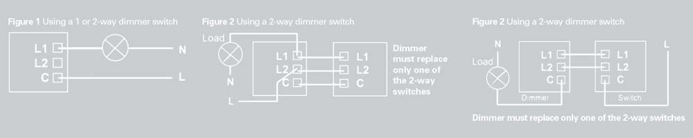
1-Way Circuits
In 1-way lighting circuits each light is controlled by one switch. Your dimmer switch should replace this switch see Figure 1. Remove your old switch and copy the wiring configuration for your dimmer switch. Connect wires either way round to the 'C' terminal and one of the 'L' terminals. The other 'L' terminal is not used in a 1-way circuit.
2-Way Circuits
2-way lighting circuits have two switches turning the same lights on and off from 2 different locations (eg. at the Top and bottom of the stairs). You must only replace one of these switches with a dimmer switch or the lights will flicker. See Figures 2 and 3 which show typical 2-way circuits. Remove your old switch and copy the wiring configuration for the dimmer. The wire(s) fitted in the 'common' terminal of the old switch should be fitted into the 'C' terminal of the dimmer switch. The wires fitted into the other two terminals of the old switch should be fitted either way round into terminals 'L1' and 'L2' of the dimmer switch.
Multi-Gang Dimmer switches
To fit 2 gang (or 3 or 4 gang) dimmer switches treat each group of terminals at the back of the unit as a separated dimmer switch wiring them into the lighting circuits as described above. If required, one terminal from each dimmer module may be joined together with a short length of wire to copy the wiring configuration of the old switch.
Jim Lawrence, The Ironworks
Lady Lane, Hadleigh
Suffolk, IP7 6BQ
Speak to one of the sales team on 01473 826685
Our telephone lines are open:
Monday - Friday: 9:30am - 5pm
Email us: sales@jim-lawrence.co.uk.